


DS200TBQCG1AAA 模拟输入毫安输入/输出 (I/O) 终端模块
产品描述
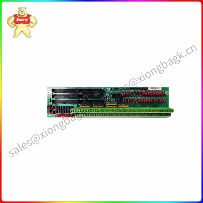
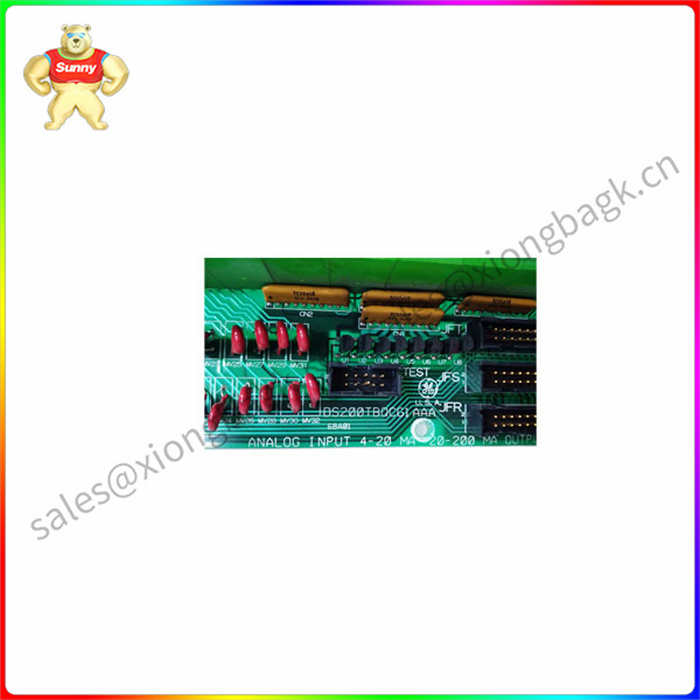
GE RST模拟终端板DS200TBQCG1AAA具有两个接线端子。每个模块包含 83 个信号线端子。GE RST模拟终端板DS200TBQCG1AAA还包含15个跳线、3个40引脚连接器和3个34引脚连接器。跳线使服务商能够修改电路板的行为,以满足驱动器操作的确切要求。当您首 次设置电路板并从工厂收到电路板时,请参阅安装说明,其中包括跳线的描述以及跳线的位置如何改变电路板的操作。当您收到电路板时,跳线处于默认位置。默认值用于大多数情况,如果默认值是您所需要的,则不需要其他步骤。
3 针跳线很容易从默认位置移动到备用位置。使用食指和拇指将跳线从默认位置移开。然后将跳线对准备用引脚并将跳线压入到位。例如,如果引脚 1 和引脚 2 是 3 针跳线中的默认位置,则将跳线插入引脚 2 和 3 以使用备用位置。
DS200TBQCG1AAA装置上的某些跳线仅供工厂使用,无法更改。通常,备用位置仅供工厂用于质量控制测试目的。更换电路板时,首先移动更换电路板上的跳线,以匹配有缺陷的电路板上的位置。
DS200TBQCG1AAA 模拟输入毫安输入/输出 (I/O) 终端模块
Product description
The GE RST analog terminal board DS200TBQCG1AAA has two terminals. Each module contains 83 signal line terminals. The GE RST analog terminal board DS200TBQCG1AAA also contains 15 jumpers, three 40-pin connectors, and three 34-pin connectors. Jumpers enable the service provider to modify the behavior of the board to meet the exact requirements of driver operation. When you first set up the board and receive the board from the factory, refer to the installation instructions, which include a description of the jumpers and how the position of the jumpers changes the operation of the board. When you receive the board, the jumper is in the default position. The default is used in most cases, and if the default is what you need, no additional steps are required.
The 3-pin jumper is easily moved from the default position to the standby position. Use your index finger and thumb to remove the jumper from its default position. Then align the jumper with the spare pin and press the jumper into place. For example, if pins 1 and 2 are the default positions in a 3-pin jumper, insert the jumper into pins 2 and 3 to use the alternate position.
Some jumpers on the DS200TBQCG1AAA device are for factory use only and cannot be changed. Typically, alternate locations are only available to factories for quality control testing purposes. When replacing a board, first move the jumper on the replacement board to match the position on the defective board.


 QQ在线客服