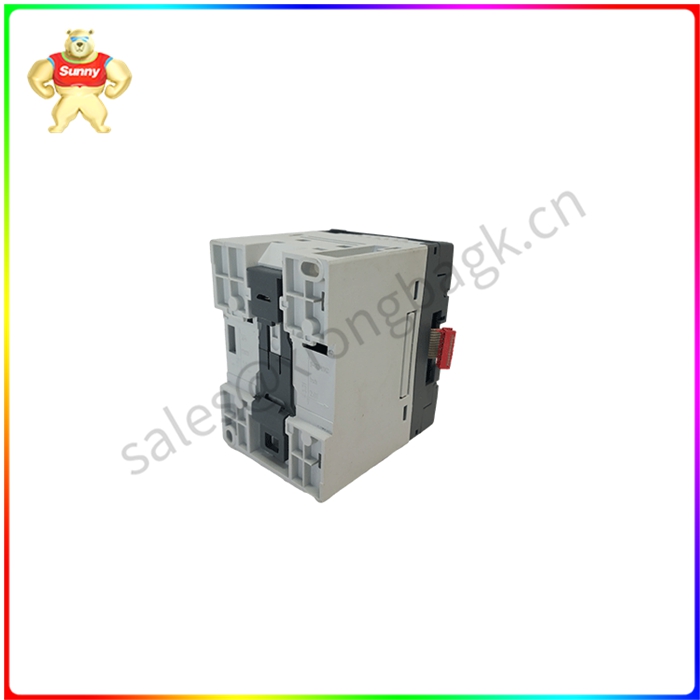
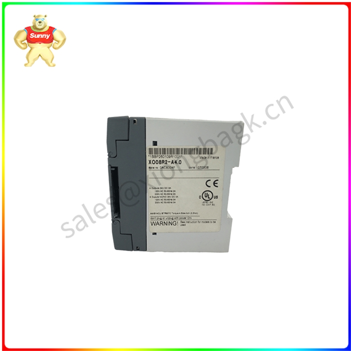

XO08R2 1SBP260109R1001 继电器输出扩展模块
简介
当输入高电平时,晶体管T1饱和导通,继电器线圈通电,触点吸合。
当输入低电平时,晶体管T1截止,继电器线圈断电,触点断开。
3.2 电路中各元器件的作用
晶体管T1为控制开关。电阻R1主要起限流作用,降低晶体管T1功耗。电阻R2使晶体管T1可靠截止。二极管D1反向续流,为三极管由导通转向关断时为继电器线圈中的提供泄放通路,并将其电压箝位在+12V上。

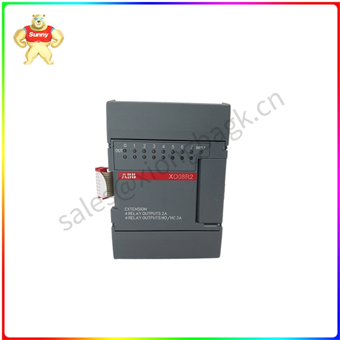
XO08R2 1SBP260109R1001 继电器输出扩展模块
1. Working principle and characteristics of electromagnetic relay
Electromagnetic relays are generally composed of iron core, coil, armature, contact reed and so on. As long as a certain voltage is added to both ends of the coil, a certain current will flow through the coil, resulting in an electromagnetic effect, and the armature will overcome the pull of the return spring under the action of electromagnetic force attraction to attract the iron core, thereby driving the moving contact of the armature and the static contact (normally open contact). When the coil is powered off, the electromagnetic suction also disappears, and the armature will return to the original position in the spring's reaction force, so that the moving contact and the original static contact (normally closed contact) are released. This suction, release, so as to achieve the purpose of conduction in the circuit, cut off. For the "normally open, normally closed" contact of the relay, it can be distinguished in this way: the static contact in the disconnected state when the relay coil is not powered on is called "normally open contact"; The static contact in the connected state is called "normally closed contact".
2. Circuit principle
2.1 Brief introduction of relays
A relay is a type of contact (or circuit) that connects or breaks an AC-DC small-capacity control loop when the input changes to a certain value
When transistors are used to drive relays, NPN triode is recommended. The specific circuit is as follows:
Brief introduction of working principle
When the input level is high, the transistor T1 saturation is on, the relay coil is energized, and the contact is drawn.
When the input level is low, the transistor T1 is off, the relay coil is powered off, and the contact is disconnected.
3.2 Functions of each component in the circuit
Transistor T1 is the control switch. Resistor R1 mainly acts as a current limiting function to reduce the power consumption of transistor T1. Resistor R2 gives transistor T1 a reliable cutoff. Diode D1 continues in reverse to provide a drain path in the relay coil for the triode to switch from on-off and clamp its voltage to +12V.
XO08R2 1SBP260109R1001 继电器输出扩展模块
| ICS | T8403 |
| ABB | PFEA111-20 |
| GE | IC754VSI12CTD |
| AUTOMATIONX | AXLINK100 |
| ABB | PM511V16 3BSE011181R1 |
| GE | 8521-EB-MT |
| RELIANCE ELECTRIC | 57C328 |


 QQ在线客服